Process of removing the circuit base from the socket.
date 10/18/2013
*****************************
Summary:
- In order to measure the resistance and capacitance from the circuit base more effectively and to draw a scheme by using kicad, I remove the circuit base from the socket by unsoldering each pin that attacthed to the circuit board.
Initial condition of the base and socket:
- see the attached base.pdf (by Professor Heppelmann) for its status before this process.
- no further major change from the status described on the pdf.
Materials used:
- Solder iron (about 300 celcius to 400 celcius when it is heated up).
- copper braid (to absord the solder after they melted)
- Chipquik tack flux ( help the melted solder to flow to the copper braid)
- 91% isopropyl alchohol (clean the flux residue on the circuit board with paintbrush afterward)
- tweezers (mostly to stablize the pin from the socket)
- pliers (change the orientation of the pins when try to take out the board)
Process details:
- Apply a small amount of flux on one connection from the pin to the board.
- After the solder iron is heat up, use it to touch the connection slightly, until the solder junction started to melt --- beware of the heat the melting the board itself, since the surface does not seem very heat-resisted.
- Using the copper braid to absorb the solder, not necessarily clean up all of them, but at least enough to not let the pin entangling on the connection.
- Since the solder liquid will be back to solid state in a few second, use the tweezer to push the pin to one side to prevent its contact to the circuit.
- repeat the above process for each pin, though the one also with capacitor attached on it may consume a bit more time due to amount of solder and removing pins among wires.
- however, since the pins are holding the circuit board like a claw holding a ball, it is unlikely to remove the circuit base from the socket without using the plier to move the tip of pins ----- further consequence need to be thought of.
- Using alcolhol to clean the residue on the board.
Time consumption:
about 20 ~25 minute for removing the circuit base ( about 12 pins attached needs to be work on), including 1~2 minute of cleaning the residue on the surface.
// since this is the first attempt, so the time consumption may actually higher than average)
*Oveall it is not considering a tough task, just require some time and concentration.
***************** Pictures taken by Professor Heppelmann, notice that the C4 capacitor is detached from the board just because it fall off during the desoldering process.*****************************
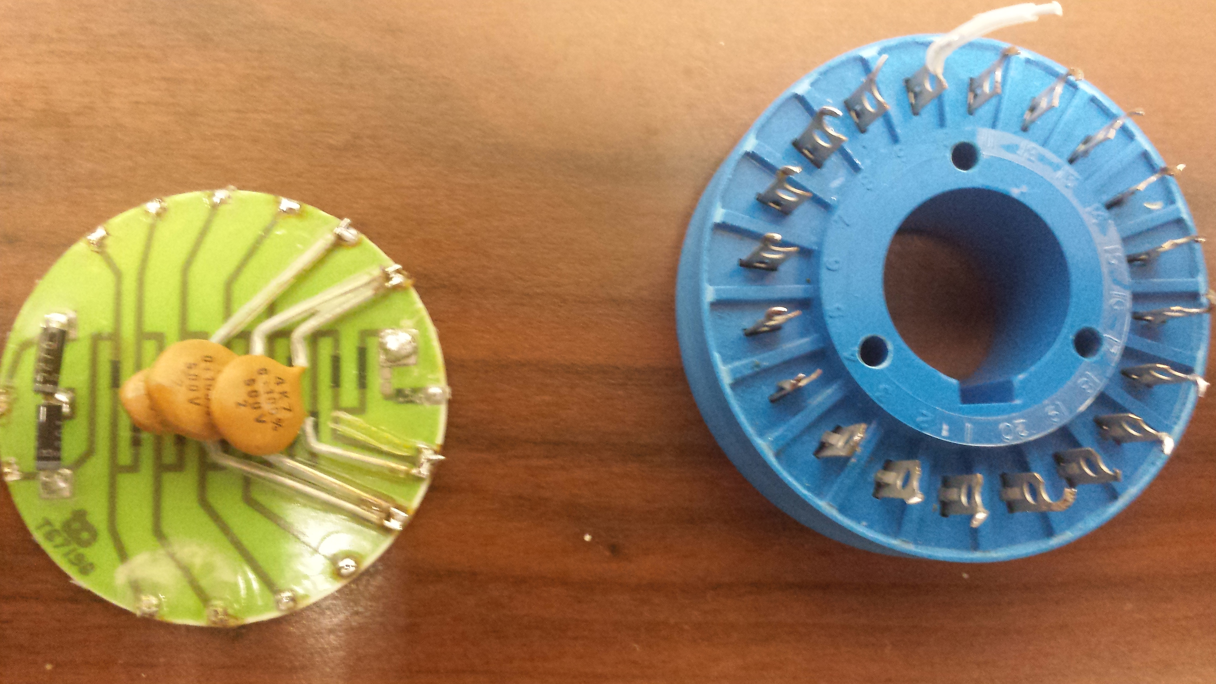
Post-test: the circuit board seems fine after the process ( I used a voltmeter to measure the resistance across the connections , the result numbers are still very closed to the measurement before doing
this dissembling work, and no further problems occur so far)
****************************************************************************************************
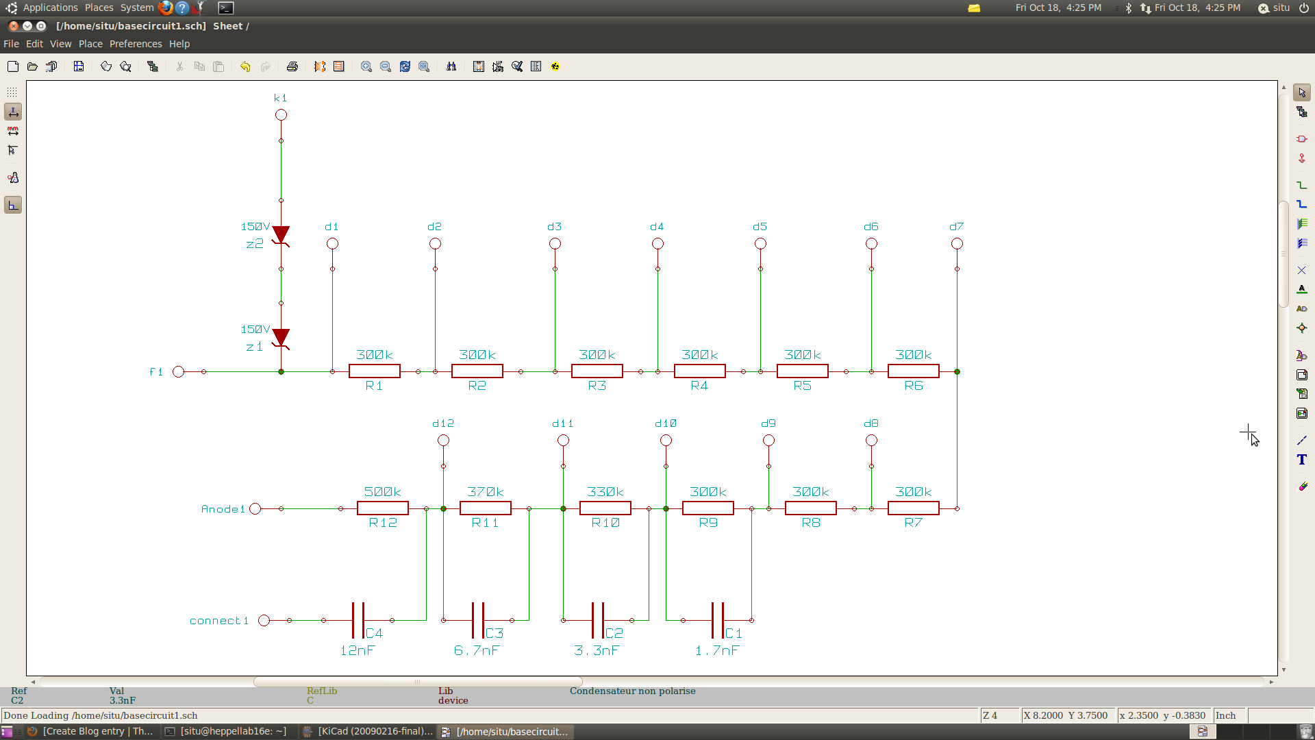
Below is the scheme drawn by using the kicad, and pin name is corresponding to the name given on the attached base.pdf file.
note: The "connect1" pin is where the C4 capacitor ( the biggest capacitor on the board) is connected to the black cap.
- situ's blog
- Login or register to post comments